Qseven-i.MX537 in conga-QEVAL Reference Manual
This document describes the conga-QEVAL carrier board Rev. 1.2 when used with the Bluetechnix Qseven-i.MX537 module.
conga-QEVAL documentation
The conga-QEVAL is an evaluation board for Qseven® modules, made by congatec.
Web site: https://www.congatec.com/qeval.html?&L=0
Datasheet, schematics, and user's guide download: https://www.congatec.com/qeval-doc.html?&L=0
Boot modes
The conga-QEVAL base board features one jumper that configures the boot mode of the Qseven-i.MX537.
SPI NOR flash
| Qseven-i.MX537 | ≥V1.0 |
| {{{3}}} | {{{4}}} |
| {{{5}}} | {{{6}}} |
| {{{7}}} | {{{8}}} |
| {{{9}}} | {{{10}}} |
| {{{11}}} | {{{12}}} |
| {{{13}}} | {{{14}}} |
| {{{15}}} | {{{16}}} |
| {{{17}}} | {{{18}}} |
| {{{19}}} | {{{20}}} |
Qseven-i.MX537 V1.0:
- Set jumper CN31 to position 1-2.
Qseven-i.MX537 ≥V1.1:
- Set jumper CN31 to position 2-3.
USB/UART boot mode
Boot via USB-OTG port.
NOTE: The mfgtool requires this boot mode to be set.
- Set jumper CN31 to position 2-3 (boot mode configuration).
- Set jumper CN55 to position 2-3.
- This uses USB port 1 (=USB-OTG) as client.
- Attach your USB cable to connector CN20 (USB B type).
Power-On/Reset
- Press button POWER (SW1) for 500ms to power up the module.
- Press button POWER (SW1) for min. 1s to induce a Linux shutdown on the module.
- Press button RESET (SW3) to reset the module.
JTAG adapter
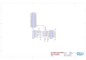
It is possible to connect an ARM JTAG debugger to the conga-QEVAL board via an adapter.
- conga-QEVAL CN35 (Feature Connector)
- conga-QEVAL CN45
- 20-pin ARM JTAG connector (e.g. Farnell order nr. 1106835)
Schematics:
Ethernet
No configuration necessary. Connect to Ethernet port on CN22.
SD/MMC card socket
- LED D12 is not used to indicate activity but signals that the socket is powered.
USB Hosts
- USB ports 0, 2, 3 (all on CN21), 4, and 5 (on CN22) of the conga-QEVAL board are connected to the MX53 USB host 1 via a USB hub on the Qseven-i.MX537.
- To enable USB port 1 (on CN21), set jumper CN55 to position 1-2.
- This selects host mode of the i.MX53 USB-OTG port.
USB Client
- To enable the USB client port (CN20), set jumper CN55 to position 2-3.
- This selects device mode of the i.MX53 USB-OTG port.
CAN Bus
- Set jumper CN62 to 1-2 (=Enable CAN termination).
- Connect CAN bus cable to CN70
- Pin 2...CAN-
- Pin 4...CAN+
We have successfully tested a bitrate of 1MBit/s.
SATA
SATA doesn't need any jumper configuration. Connect your SATA device to SATA0 port (CN17).
LVDS display
We have tested LVDS0 and LVDS1 outputs with the following display:
- Toshiba LT104AC36000
- Configure the following jumpers:
- Set jumper CN11 to position 1-2 (Selects 12V as Backlight voltage)
- Set jumper CN13 to position 1-2 (Selects 3V3 as LCD voltage)
- Set jumper CN14 to position 1-2 (Sets backlight enable signal as high-active)
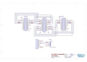
We used the following adapter to connect the display
- conga-QEVAL CN12 (LVDS connector)
- conga-QEVAL CN15 (LCD Power connector)
- Toshiba CN1 (e.g. Digikey order nr. H10161-ND)
- Toshiba CN2 (e.g. Farnell order nr. 1125375)
Schematics:
Speaker
U-Boot makes a short beep via the speaker on the conga-QEVAL. (This is no PWM signal, but just GPIO toggling.)

