Argos3D Quick Start Guide
Thank you for choosing an Argos3D ToF camera! This quick start guide will help you get started with the device. Following this guide, you will be able visualize 3D ToF data on your PC in no time.
Unboxing
An Argos3D kit typically consists of:
- Argos3D ToF camera,
- Ethernet cable,
- Power supply (including DC jack cable for Argos3D-P32x and P33x),
- Mounting kit (P2xx Mounting Kit for Argos3D-P22x and P23x, VESA adapter for Argos3D-P32x and P33x),
- Interface break-out board (for Argos3D-P22x and P23x).
Note: The power supply's operating temperature is specified from 0 to +40°C. This does not represent the effective working temperature of the Argos3D ToF camera.
Connecting
To use the camera, you need to connect the power supply and the ethernet cable to it. The exact steps of this process depend on the camera model and must be followed in the given order.

For the Argos3D-P22x and P23x:
- Attach the interface break-out board to the common connector on the camera.
- Connect the power supply to the interface break-out board (see schematic on the right). A 12-30 V DC power supply is required with the following connector pin assignment: Pin#1 - +12 to +30V, Pin#2 - GND. Wait approximately 20s for the camera to boot.
Note: The power supply connector is protected against wrong polarity but the camera will not work in case you do not use the correct polarity. If the camera does not work, please check the power supply polarity!
- Connect the ethernet cable to the interface break-out board (see schematic on the right).


For the Argos3D-P32x and P33x:
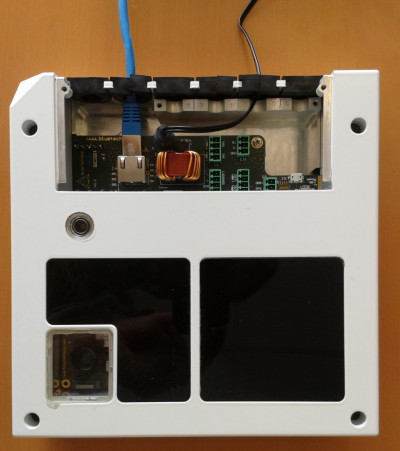
- Unscrew the two screws on the front of the camera and remove the connector compartment lid.
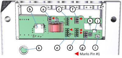
- Connect the power supply to the appropriate connector (see schematic on the right). A 12-30 V DC power supply is required with the following connector pin assignment: Pin#1 - +12 to +30V, Pin#2 - GND. Wait approximately 20s for the camera to boot.
Note: The power supply connector is protected against wrong polarity but the camera will not work in case you do not use the correct polarity. If the camera does not work, please check the power supply polarity!
- Connect the ethernet cable to the appropriate connector (see schematic on the right).

For more information about the available connectors and interfaces, consult the Hardware User Manual for your camera model.
Software download & Network setup
| BltToFSuite system requirements | |
|---|---|
| Operating system | Microsoft Windows 7/8/10/Vista |
| CPU | 32-bit (x68) or 64-bit (x64), 2GHz dual-core or higher |
| RAM | 2GB or higher |
| Interfaces | Dedicated Ethernet port |
The BltToFSuite is a powerful tool to visualize the data obtained by your camera and to modify camera settings. Download the application and unzip the .zip file.
Note: Should you experience issues with this step, be aware of a common problem with blocked .zip files in Windows, and consult the BltToFSuite User Manual.
Place the camera on your desk approximately 50cm in front of you and connect it to a Network Interface Card (NIC) of your PC with the ethernet cable. Give this NIC the IP address 192.168.0.1 with a subnet mask of 255.255.255.0. By default, the camera uses the IP address 192.168.0.10 with subnet mask 255.255.255.0. No driver has to be installed on your PC.
Using the BltToFSuite

You can connect to your camera by either using the "Device Discovery" tool or by entering the camera network settings manually.
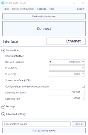
To discover the camera in the network, click the "Find available devices" button in the connection window of the BltToFSuite. This opens the "Discovery" window and a search for cameras in the network is initiated. Information about the connected camera appears after a few seconds of searching. Click the "Connect" button above the camera details to establish a connection to the discovered camera.
Alternatively, the camera network settings can be entered manually in the "Connection" window. If this is your first use of the BltToFSuite, the network parameters provided in the "Connection" window correspond to the default parameters of the camera and you are able to connect without modifying them. Click the "Connect" button at the top of the window to establish a connection to the camera.
Note: Some firewalls may inhibit data traffic between your PC and the camera. Adjust the firewall settings if necessary to allow communication between your PC and the camera.
Note: If you experience issues with the software, consult the BltToFSuite User Manual and the ToF FAQ page.
Once a connection has been established, the depth and amplitude data are shown in the "Visualizer" window and you can inspect the world around you in 3D.
Go further
After these first steps, you can learn more about your camera, compatible software, tips & tricks, and ToF technology on these pages:
- Information specific to your camera model: