ToF User Guide
The ToF User Guide is intended to help you get started with your ToF camera and generally gain a deeper understanding of this system. The User Guide illustrates how to set up connections between the camera and your computer and how to use various features of the camera to optimize the 3D data you obtain. The images and videos in this User Guide were produced using the Argos3D P330 camera. However, the described workflows can be applied to other models in the same manner. The easiest ways to control and obtain data from your camera are the BltTofSuite, which allows interaction with the camera via a GUI, and the BltTofApi, a library which allows interaction with the camera via C/C++ scripts. While the User Guides show these procedures in the BltTofSuite, they can be readily reproduced using the BltTofApi. Examples illustrating the use of the BltTofApi can be found here.
Getting Started
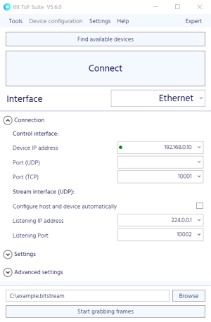
Your camera must be connected to the appropriate power supply (check the Hardware User Manual of your camera model) and to your computer via Ethernet or USB. Once the camera is running, you can establish a connection to your computer using the factory-default network settings shown in the image to the left. Make sure that your computer’s network adapter is configured to an IP address within the same subnet as the camera. Default values for your network adapter are 192.168.0.1 for the IP address and 255.255.255.0 for the subnet mask. You also need to make sure that your firewall does not inhibit network traffic to and from the camera, in particular UDP multicast traffic.
Alternatively, connected cameras and their network settings can be found using the device discovery feature if your camera supports it. This feature is particularly helpful if you are not sure whether your camera is configured to factory-default network settings. The following camera models support device discovery: the Argos3D P22x, P23x, P32x, and P33x series, and the Sentis3D M421.
In addition, the connection parameters of the camera can be configured automatically. If this feature is enabled, the camera will be configured automatically in such a way that the UDP stream is directed to your computer's network adapter when a connection attempt is made.
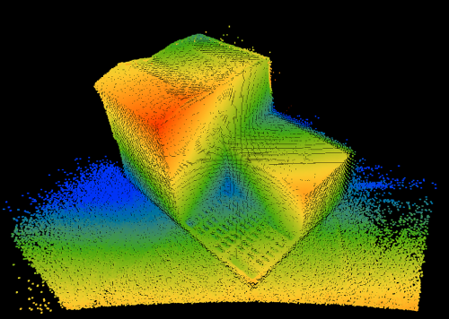
As soon as the connection to the camera is established, you can see the data obtained by the camera in the Visualizer window of the BltTofSuite. By default, the camera provides distance and amplitude data. By changing the Frame mode from "Distance, Amplitude" to "X, Y, Z", the data can be visualized as a point cloud using the "Model3d (Point cloud)" tool.
Optimizing the Distance Data and 3D Point Cloud
Depending on your application, the 3D data you obtain from the camera might have to meet quality criteria regarding, for example, the measurement accuracy, the covered distance range, or the noise level. The following sections will describe how to optimize your point cloud by modifying the modulation frequency and integration time, and by applying spatial and temporal filters.
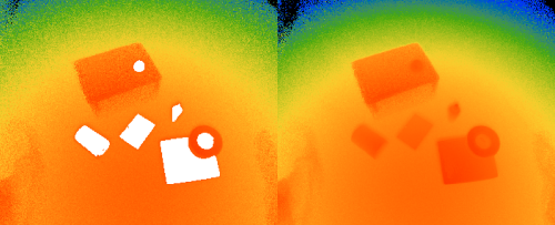
The example scene used in this User Guide is purposefully chosen to be challenging for ToF cameras: The scene contains objects of varying size, shape, reflectivity, and distance to the camera. This will allow us to explore several camera functionalities that will ultimately provide a high-quality 3D point cloud despite the difficulties presented by the observed scene.
Modulation Frequency


One of the basic parameters to adapt is the modulation frequency. A lower modulation frequency is associated with a larger disambiguity range, but also with lower precision and accuracy. When choosing the modulation frequency, you should therefore consider the range in distance that you would like to measure, and which level of noise is acceptable for your application. The factory-default value of the modulation frequency is 20MHz for the Argos3D P330, which corresponds to a disambiguity range of approximately 7.5 m. The image on the right shows the effect of varying the modulation frequency.
For the Argos3D P330, the highest possible modulation frequency is 80 MHz. At this modulation frequency, the edge of the disambiguity range at approximately 1.8 m is visible in the top corners of the image. Here, objects just beyond the disambiguity range are seen as very close to the camera. For our example scene, we choose a modulation frequency of 40 MHz, corresponding to a disambiguity range of approximately 3.7 m. If your application requires the benefits of both low and high modulation frequencies, consider combining frames with two different modulation frequencies (Vernier mode). The available modulation frequencies for a specific camera model can be found in the respective User Manual.
Integration Time

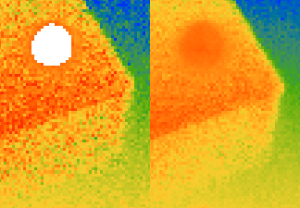
The integration time influences the noise level and the tendency for objects in your scene to be under- or overexposed. Higher integration times produce frames with lower noise levels, but objects that have a high reflectivity and/or are placed close to the camera might be overexposed. The distances measured at under- or overexposed pixels are generally not reliable and are therefore flagged accordingly. By default, the integration time is set to 1000 μs. For our example scene, this results in an overexposure of several objects, as seen in the following image. A lower integration time of 310 μs means that reliable distances to these objects can be obtained, but parts of the black box in the back of the scene are underexposed.
Our example scene contains objects with large differences in reflectivity. For example, a white cardboard box and a white metal cylinder are placed close to the camera, while a black plastic box is placed further away from the camera. In cases like this, choosing an integration time that neither under- nor overexposes any part of the scene might be impossible. Fortunately, the HDR feature provides a way of combining several frames with different integration times.
Another method to avoid under- or overexposure is to modify the confidence thresholds that define below/above which amplitude value pixels are flagged as under-/overexposed. This feature should be used only if varying the integration time and HDR mode cannot provide satisfying results, and if the reliability of distance measurements in under-/overexposed regions is not critical.
Spatial and Temporal Filtering
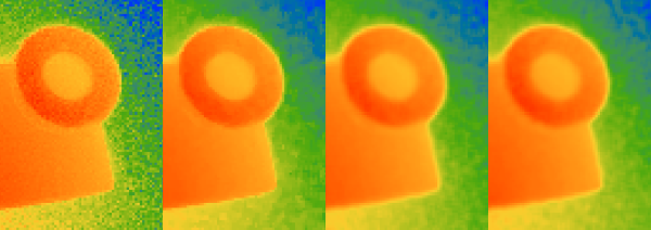
To reduce noise in the 3D point cloud, spatial and temporal filters can be applied to the distance data as an additional processing stage. A comparison of an unfiltered frame with frames with a median, average and bilateral filter is shown on the right.
Filters can be added to the processing chain by writing the corresponding registers. The image to the right shows which registers need to be adapted to use a median filter with one iteration.

The distance data can also be averaged over time, i.e. over several consecutive frames, by applying frame average or sliding average filters. Both the frame average and the sliding average filter calculate the average of several frames (for example 5 frames) for each pixel. Using the frame average filter, the resulting framerate is reduced (for example by a factor of five). The sliding average filter does not necessarily reduce the framerate since it continuously calculates the average from the previous captured frames. The image to the right shows the noise reduction due to temporal filtering.
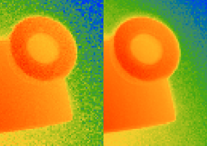
If desired, the amplitude data can be spatially and temporally filtered in a similar fashion.
The following camera models support image filtering: the Argos3D P22x, P23x, P32x, and P33x series, and the Sentis3D M421, M520 and M530.
HDR Mode

Using HDR mode, several frames with different integration times can be combined to one frame. For our example scene, two frames with integration times of 310 and 1000 μs are combined. The image on the right shows that HDR mode allows for reliable distance measurements and comparably low noise in regions that would be under- or overexposed when using only a single integration time.

You can configure your camera to use HDR mode by writing the required settings to the corresponding registers. The image on the right shows which registers need to be adapted to use HDR mode with two different integration times (depending on your camera model, up to four are possible).
The following camera models support HDR mode: the Argos3D P23x, P32x, and P33x series, and the Sentis3D M530.
Vernier Mode

Similar to HDR mode, several frames with different modulation frequencies can be combined to one frame using Vernier mode. Vernier mode combines the advantages of high modulation frequencies (high accuracy and precision) and low modulation frequencies (large disambiguity range).
To illustrate this, a different example scene is shown on the right, which consists of a white wall with a length of approximately 3.5 metres. Using a high modulation frequency of 80 MHz, the disambiguity range is approximately 1.8 meters - not enought to cover the total length of the wall. Therefore, a jump in distance values is visible at a distance of approximately 1.8 meters. At 20 MHz, the disambiguity range (approximately 7.5 meters) exceeds the length of the wall and no jumps in the data can be seen. However, the data quality is generally lower than for a modulation frequency of 80 MHz. Combining frames with different modulation frequencies can both avoid discontinuities in the distance data and provide high data quality.

The following camera models support Vernier mode: the Argos3D P23x and P33x series.
Framerate Considerations

The achievable framerate is limited by the time needed to capture and process a frame. Capturing sequences (e.g. for HDR or Vernier mode) and additional image processing (i.e. spatial and temporal filtering) extend the total time required to produce a frame and determine the maximum achievable framerate. The framerate produced by the camera and received by the BltTofSuite or the BltTofApi thus might be lower than the framerate requested by the user. In the BltTofSuite, these values can be compared directly (see image to the right). It is advised to set the framerate to a value that can be produced by the camera to reduce the number of frames that need to be dropped due to incomplete processing.
Saving and Replaying Data
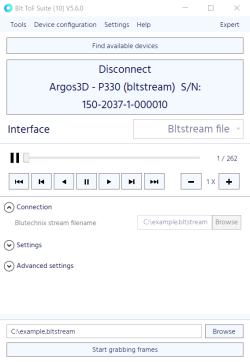
Both the BltTofApi and the BltTofSuite allow you to save the captured data to a file and replay it later. The frames are saved in the bltstream file format and include some metadata such as the integration time and modulation frequency that were used.
To save frames to a file using the BltTofSuite, establish a connection to your ToF camera, choose a filepath and name and click the "Start grabbing" button at the bottom of the connection window. If you want to stop saving frames, click the "Stop grabbing" button at the bottom of the connection window.
To replay a bltstream file using the BltTofSuite, select "bltstream file" in the "Interface" dropdown menu in the connection window. Insert the filepath and click "Connect". Alternatively, you can drag-and-drop a bltstream file into the connection window. You can now navigate through the saved frames using the pause/play/skip buttons and choose the replay speed. If you want to close the bltstream file, click the "Disconnect" button at the top of the connection window.